Posey's Tips & Tricks
Exploring CPU Groups in Windows Server 2016 Hyper-V, Part 1
Microsoft lets Windows Server 2016 users allocate CPU resources at a much more granular level than before. To get started, here's an overview of basic CPU topology.
Allocating CPU resources in Hyper-V has always been somewhat simplistic.
Through the Hyper-V Manager, administrators are able to allocate virtual processors to individual virtual machines (VMs). The Hyper-V Manager also provides a variety of resource-control settings that admins can use to set a VM reserve or to allocate a certain percentage of the total system resources (among other things).
In Windows Server 2016, however, Microsoft has quietly given its customers the ability to allocate CPU resources in a much more granular way.
It is now possible. for example, to force workloads to run on specific CPUs. You can also impose a CPU usage cap on an entire group of VMs so that those machines may not collectively consume CPU resources beyond a limit that you put in place. If you have a private cloud environment, you can even use the new CPU groups feature to create various classes of service.
If you have spent much time working with Windows Server 2016 Hyper-V, then you have no doubt noticed that the settings within the Hyper-V Manager are nearly identical to those that exist in Windows Server 2012 R2.
As I said before, though, Microsoft introduced granular CPU resource controls quietly. You won't find a CPU Groups setting in Hyper-V Manager, or in any of the other usual management tools. Instead, you will have to download a dedicated command-line tool from Microsoft. The tool is called CPUGroups.exe, and you can download it here. Keep in mind that this tool will only run on Windows Server 2016.
So let's take a look at how to use this tool. If you look at Figure 1, you can see that I have entered the GetCPUGroups command into an administrative command prompt, and also specified the GetCPUTopology parameter. The results in this case are spread across eight lines and several columns. So let's take a look at what this information means.
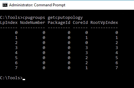 Figure 1: This is how you retrieve CPU topology information.
The first column, the one marked LpIndex, shows the number of logical processors within the system. My lab server includes eight logical processors, and you can see those listed (from 0 to 7) in the LpIndex column.
The resulting output also contains columns reflecting the node number and the package ID. A CPU package essentially just refers to a physical CPU. The server from which the screen capture was taken is only equipped with a single socket (a single CPU), so every entry in the PackageID column reads 0, indicating that all of the logical processors are associated with physical CPU number 0. If this were a dual-socket system, however, then half of the entries in the PackageID column would be 0 and the other half would be 1.
The NodeNumber column reflects the NUMA node that each logical processor is bound to. Again, this particular machine is not equipped with multiple NUMA nodes, so each entry in the NodeNumber column is set to 0.
The fourth column is the CoreID column. As its name implies, this column lists individual CPU cores. As you take a closer look at the figure, you will notice that there is not a one-to-one relationship between logical processors (the LpIndex column) and CPU cores (the CoreID column). This particular server has eight logical processors, but only four CPU cores.
We can also see that logical processor numbers 0 and 2 are mapped to core 0. Likewise, core 0 is mapped to package 0 (of course, this machine only has one package).
Similarly, logical processors number 1 and 7 are mapped to core number 1, which also resides within package 0. Hence, we can use the information shown in this table to begin to get a sense of the server's CPU architecture.
The last column shown in the chart is the RootVPIndex column. As you may know, Hyper-V makes use of a series of partitions. There is a root partition where the host operating system runs, and there are also VM partitions. The RootVPIndex column tells us whether a virtual processor can be used by the root partition, or if it is available only for use by VM partitions.
If the RootVPIndex column shows a value of 0 or higher, then the corresponding logical processor can be used by Hyper-V's root partition. Conversely, logical processors with a RootVPIndex of -1 can only be used by guest partitions.
In this case, all of the values are 0 or higher, so all of the logical processors can be used by the root partition.
Now that I have explained the basic CPU topology information, I want to come back in Part 2 of this series and show you how you can use this tool to allocate CPU resources within Hyper-V.
About the Author
Brien Posey is a 22-time Microsoft MVP with decades of IT experience. As a freelance writer, Posey has written thousands of articles and contributed to several dozen books on a wide variety of IT topics. Prior to going freelance, Posey was a CIO for a national chain of hospitals and health care facilities. He has also served as a network administrator for some of the country's largest insurance companies and for the Department of Defense at Fort Knox. In addition to his continued work in IT, Posey has spent the last several years actively training as a commercial scientist-astronaut candidate in preparation to fly on a mission to study polar mesospheric clouds from space. You can follow his spaceflight training on his Web site.